Providing a general solution to this problem is not an easy task as
many intertwined aspects of the problem have to be taken into account
simultaneously.
Having the ability to describe a first level of mapping that would direct the xSTreamC
compiler fusion of entities is an important step to control. As the
xSTreamC model of communications is execution resource agnostic (XPE and HW block can use the same communication mechanism) the application should be kept architecture independent.
A text based file (XML,
specific language, ...) could direct the compiler instructing it on which
filters should be merged and which ones are implemented using an
HW block and must be left alone.
This text based file could then be generated by a more complex environment based on execution results.
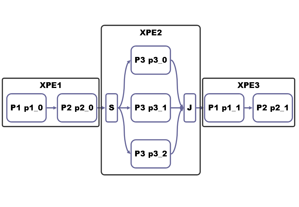
A mapping file is of course defined for a given application, let’s use the following simple example
pipeline application()
{
  P1 p1_0;
  P2 p2_0;
  split {
    P3 p3_0;
    P3 p3_1;
    P3 p3_2;
  } join;
  P1 p1_1;
  P2 p2_1;
}
|  |
One could specify the following mapping this way:
<xpe name="xpe1">
  <filter instance="p1_0" />
  <filter instance="p2_0" />
</xpe>
<xpe name="xpe2">
  <filter instance="p3_0" />
  <filter instance="p3_1" />
  <filter instance="p3_2" />
</xpe>
<xpe name="xpe3">
  <filter instance="p1_1" />
  <filter instance="p2_1" />
</xpe>
|  |
As XML is extensible we could think of adding any relevant attributes such as:
Or perhaps it would be easier to specify it in the order of the pipeline description
pros:
Matches the pipeline description hierarchy
A skeleton of the mapping file can be dumped by
xSTreamC easily.
Two different mappings have a structure very close to each other. Only the selected node IDs will change ?
Internal pipelines (no example here
!) would be dumped the same way, and so, the mapping of one of these
could be used as is (no changes of the instance names !)
cons:
<pipeline name="application">
  <filter name="p1_0">
    <node number="1"/>
  </filter>
  <filter name="p2_0" />
    <node number="1"/>
  </filter>
  <filter name="p3_0" />
    <node number="2"/>
  </filter>
  <filter name="p3_1" />
    <node number="2"/>
  </filter>
  <filter name="p3_2" />
    <node number="2"/>
  </filter>
  <filter name="p1_1" />
    <node number="3"/>
  </filter>
  <filter name="p2_1" />
    <node number="3"/>
  </filter>
</pipeline> | |
To have a shorter descriptions the node could be a filter attribute generated with no value by
xSTreamC.
Maybe it would also be interesting if we could keep the pipeline structure ?
<node id="1" type="xPE" peid="0" ht="0" />
<node id="2" type="xPE" peid="1" ht="0" />
<node id="3" type="xPE" peid="2" ht="0" />
<pipeline name="application">
  <filter name="p1_0" node="1"/>
  <filter name="p2_0" node="1" backlogsize="1024" />
  <splijoin>
    <split node="2" />
    <filter name="p3_0" node="2"/>
    <filter name="p3_1" node="2"/>
    <filter name="p3_2" node="2"/>
    <join node="2" />
  </splitjoin>
  <filter name="j" node="2"/>
  <filter name="p1_1" node="3"/>
  <filter name="p2_1" node="3"/>
</pipeline> | |
We need to add some other attributes attached to a filter, in order to map filters on
XPE resources:
Mips budget
Local memory size (some are statically known, but estimation of dynamic memory allocation may be useful)
Input/Output bandwidth
number of queues (for shared resource)
floating point unit?
Mapping is a problem of filter fusion AND resource sharing. We also
need to add some Platform characteristics in order to ensure the
mapping is possible :
These information could be stored in a separate file?? (but multiply the number of files...) Here is the proposal :
   // platform informations
   //------------------------
<node id="1" type="xPE" peid="0" ht="0" mem = "64kB" mips="50000" fp="true"/>
<node id="2" type="xPE" peid="1" ht="0" mem = "64kB" mips="50000"/>
<node id="3" type="xPE" peid="2" ht="0" mem = "64kB" mips="50000"/>
<node id="4" type="Texture_unit" queue_in="10", queue_out="10"/>
   // application informations
   //--------------------------
<pipeline name="application">
  <filter name="p1_0" node="1" mips="20" dyn_alloc="5kB"  bw_in="100MB" bw_out="300MB"/>
  <filter name="p2_0" node="1" backlogsize="1024" mips="20" dyn_alloc="5kB"  bw_in="100MB" bw_out="300MB"/>
  <splijoin>
    <split node="2" mips="20" dyn_alloc="5kB" />
    <filter name="p3_0" node="2" mips="20" bw_in="10MB" bw_out="30MB"/>
    <filter name="p3_1" node="2" mips="20" bw_in="10MB" bw_out="30MB"/>
    <filter name="p3_2" node="2" mips="20" bw_in="10MB" bw_out="30MB"/>
    <join node="2" mips="20" dyn_alloc="5kB"/>
  </splitjoin>
  <filter name="p1_1" node="3" mips="200" bw_in="10MB" bw_out="20MB"/>
  <filter name="p2_1" node="3" mips="50" dyn_alloc="15kB"  bw_in="100MB" bw_out="300MB"/>
</pipeline> | |
Let’s summarize the attributes of the examples above...
PE = Processing Element. xPE is only one type of it. Here is a list of attributes for the PEs. They should represent capabilities of the Processing Element.
type (”xPE”, “hardware”): specifies the type of the processing element
backlogsize: Size of memory allocated for the queues.
frequency: might this be useful?
mem: Amount of memory available.
infifo: Number of input queues.
outfifo: Number of output queues.
inoutfifo: Number of queues able to be used as in or out queues.
nbht: Number of hardware threads.
fp (true/false): Whether it has floating point operations.
simd (true/false): Whether it has SIMD operations.
Queues should be described inside a PE, possibly specilizing applicable attributes:
<pe id=0 infifo=2 outfifo=1 backlogsize=1024>
  <queue type=in />
  <queue type=in backlogsize=128/>
  <queue type=out />
</pe>
Here is a list of attributes for the (virtual) nodes. They should represent the definition of this virtual node, and possibly redefine attributes of the PE.
Here is a list of attributes to attach to a given filter. They shoul represent needs of the filter, or mapping information (the node, c.f. node)
node: The virtual node it’s mapped upon

Mapping two filters to the same node will have as an effect to merge them (if possible), or to fail !!
mem: Estimation of the memory needed for thie filter.
fp (true/false): whether it would benefit of having a floating point unit.
simd (true/false): whether it would benefit of having a SIMD unit.
If two or more filters are requested a mapping on the same node,
they should be merged or the alternative is not only to fail but a
virtual merge onto multiple threads (logical and/or physical) that use a queue loopback features (push/pop queues or connected pairs of push and pop queues).
Throughput may be a required attributes as well : either frequency/ bus
width/ efficiency, or bandwidth. It seems required in order to identify
congestion , in case of split/ join mapped on different
XPE, for
NOC router charge balancing, or bottleneck identification. Other Platform Hardware ressource ?
DDR bandwidth ?: mapping is less
concerned with this, but application requires such information,
especially when we will load several pipeline on the
XPE fabric : 3D graphics, audio, ...
DMA : again, mapping is less concerned with this, but application : description of number of channels required?